
Which CAD Software Should a Solo Inventor Start With?
A Pick-by-Project Guide
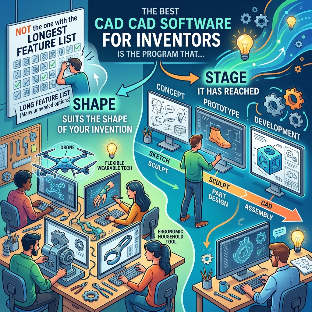
The best CAD software for inventors is the program that suits the shape of your invention and the stage it has reached, not the one with the longest feature list. If your idea is a blocky gadget, a free browser tool will do; if it has moving parts, you want a parametric program that remembers your dimensions.
Most first-timers pick whatever a video tutorial used and then spend three weeks fighting it. Five minutes of matching up front saves most of that.
Which CAD program should an inventor pick?
Here is the quick version, sorted by what you are making:
- A rough shape you want to see and hold: start with a beginner-friendly, browser-based tool built from simple solids, such as Tinkercad.
- An organic, curvy form (a grip, a toy, a sculpted housing): a mesh or sculpting program such as Blender suits the look, though it is weak on exact measurements.
- Anything with parts that fit, slide or rotate: a parametric solid modeller, such as Fusion, Onshape, FreeCAD or SolidWorks.
- Flat pieces cut from sheet (laser cut, CNC, folded): anything that exports clean 2D outlines, ideally one that also handles sheet-metal or flat-pattern work.
If you only remember one rule, make it this: parametric tools cost more learning time up front and pay it back every time you change your mind. Inventors change their minds constantly… it is practically the job description. 😉
What are you actually inventing? Four project types and the CAD style each one wants
CAD programs fall into a few styles, and each style is good at one kind of thinking. Match the style to your idea before you compare brand names.
1. The napkin shape. You have a form in your head and want to see whether it looks right on a desk. Proportions matter more than millimetres. Direct, push-and-pull modelling or simple solid blocks get you there fastest, and you can stack shapes in an evening. Precision comes later.
2. The working mechanism. A latch, a hinge, a gear train, a clamp. Here the dimensions drive each other: change a shaft diameter and the hole it sits in should follow. That is what parametric modelling does, because it stores your sketches and measurements as rules you can edit. You also want assemblies, so you can check that part A really does clear part B when it swings.
3. The electronics enclosure. A box with a lid, screw posts, a cut-out for a USB port, a window for a display. It is repetitive and measurement-heavy, which suits parametric tools. You will also want to import the dimensions of your circuit board or components so the case fits them. Check that your chosen program can bring in a STEP model of a part, since many component makers publish those.
4. The flat-pack or sheet idea. If your invention is cut from plywood, acrylic or sheet metal, you are working mostly in two dimensions. Your main needs are accurate outlines, consistent material thickness and a DXF or SVG export. A full 3D suite can be more than you need, though 3D helps when you want to check how the pieces fold or slot together.
Plenty of inventions mix two of these. A handheld gadget might begin as a napkin shape and become an enclosure with a mechanism inside. Pick the style your riskiest part needs, because that part will break your model first.
Which tools are easiest to start with, and where do they run out of road?
Ease of learning and professional usefulness pull in opposite directions, so it helps to see both sides of each tool.
Tinkercad. It runs in a browser and builds models by combining and subtracting basic shapes. Most people can make something printable in an afternoon. Its limits show up when you need precise sketches, controlled curves, many parts in one assembly or a detailed engineering drawing. It is a good place to test whether a shape feels right, and a poor place to finalise a design for a manufacturer.
SketchUp-style push-pull tools. These are quick for boxes, furniture and enclosures with flat faces. They are less comfortable once you need tight tolerances or complex curved parts, so check how well your target use is supported before you commit.
Blender. It is free and very good at forms and renders, which makes it handy for a picture to show someone. It models with meshes, not engineered solids, so precise dimensions and clean manufacturing files take extra effort. Treat it as a design-look tool, and move to a solid modeller when the object has to be made.
Fusion, Onshape and FreeCAD. These are parametric solid modellers and cost more learning time at the start. A first small part might take a weekend to feel comfortable with, which is an honest price for a program you can keep growing into. They handle sketches, assemblies, and exports for printing and machining.
Where a tool runs out of road is usually a project demand, not a skill ceiling. The moment you need to change a dimension and watch ten parts update, or hand over a clean file for manufacturing, a simple tool stops being enough.
Which tools do professionals and manufacturers actually expect to receive?
Manufacturers rarely care which program you drew in. They care whether they can open your file, measure it and trust it.
Professional engineering teams commonly work in programs such as SolidWorks, Inventor, Creo or NX, and many small shops use Fusion or Onshape. If you use one of those, a shop that uses the same one can open your native file directly. That is a convenience, not a requirement.
The universal hand-off is a neutral exchange file. STEP is the usual choice for solid parts, since almost every professional CAD program can read it. For anything that gets made by machining, moulding or sheet cutting, a supplier will often also ask for a dimensioned PDF drawing that states tolerances and materials. Ask your intended maker or manufacturer early what they want, because the answer varies by process and by shop.
So the practical question for an inventor is not “which program do professionals use?” but “can my program export STEP and a clear drawing?” Most of the serious options can, which is the real test.
Can free or hobby-friendly CAD carry a real invention? What to check in the licence before you commit
Often yes, but read the licence first, because free tiers come with conditions and those conditions change. Terms differ by program and get updated, so check the current wording on the vendor’s own site, and consult a professional if the stakes are high.
Before you invest weeks, check these points:
- Commercial use. Does the free or personal licence allow you to sell a product designed with it, or to design for clients? Some are restricted to non-commercial use or personal projects.
- Income or business limits. Some licences allow free use only below a certain revenue or business status. If you hope to sell, this matters.
- Public versus private files. Some free cloud plans make your documents visible to others. For an unpublished invention, that is a serious issue. If you are worried about protecting an idea, read intellectual property protection for independent inventors before you upload anything.
- Export access. Can you still export STEP, STL or DXF on the free plan? Check the list, not just the headline.
- What happens if the terms change. Keep local copies of every file in neutral formats, so a policy shift cannot lock you out of your own design.
- Ownership. Check the terms for any statement about who owns what you create or upload.
Open-source programs such as FreeCAD generally avoid cloud and revenue conditions, since your files live on your own machine. The trade-off is a rougher interface and more patience when something misbehaves.
How to test-drive a CAD program in one weekend with a single small part from your own idea
Skip the tutorial model of somebody else’s teapot. Use a real part from your own invention, small enough to finish: a bracket, a clip, a knob, a lid, a hinge half. A real part exposes the problems you will actually have.
- Saturday morning: watch one beginner tutorial for the program, then model your part with roughly correct dimensions.
- Saturday afternoon: change a key dimension, such as a hole diameter or wall thickness. Note how much work it takes to update the model. This is the clearest test of whether the program is parametric in a way you can live with.
- Sunday morning: model a second part that must fit the first, and check the fit.
- Sunday afternoon: export a STEP file and an STL file, then open both in a different free viewer or program. If the geometry survives, your hand-off will too.
Afterwards, ask yourself three plain questions. Did I understand what the program was doing? Could I fix my own mistakes without searching for an hour? Do I want to open it again on Monday? If the answer to the last one is yes, you have found your program. If not, try the next one, since you have only lost a weekend.
What file formats should you save so a maker, a 3D printer or a patent attorney can open your work?
Save more than one version of each design. Your native file keeps full editing ability inside your own program, and exported files serve everyone else.
Who needs it Format to save A manufacturer or machinist STEP, plus a dimensioned PDF drawing A 3D printer or print service STL or 3MF A laser cutter or sheet-cutting shop DXF or SVG A patent attorney PDF drawings and clear images; ask what they want Yourself, later The native file, with a dated copy
For printing in particular, the settings and file choices have their own pitfalls, which the beginner’s guide to 3D printing prototypes for inventors covers in detail.
For a patent attorney, the safest approach is to ask what they need. Requirements for drawings are specific and vary by jurisdiction, so provide clear views of your design and let them tell you which format and level of detail they require.
Name your files by version and date, such as “latch_v03_2026-11-08”, and never overwrite the last working copy. Future you will be grateful.
When to stop modelling and start building: pairing your CAD file with real parts
CAD makes it easy to keep refining forever. A model can look finished while still hiding problems that only a physical part reveals, such as a spring that is too stiff, a screw that is too long or a surface that feels wrong in the hand.
A good time to switch is when the model answers the questions that matter at this stage: does it fit, does it move, does it look right. At that point, print it, cut it or build it, and test it with your hands.
Real components also have real dimensions. Motors, fasteners, bearings and switches come with their own sizes, and your design should be built around what you can actually buy. Find those parts first, download their dimensions where the maker offers them, and place them in your model. Where inventors actually find the parts their prototypes need walks through sourcing them, so your CAD file and your parts bin agree before you commit to a build.
The first prototype will probably be wrong in a useful way. That is what it is for.
Tell me in the comments which CAD program you use, what you built with it, and the one thing you wish someone had warned you about.
Another inventor is probably hunting for exactly that answer… ☕

